Space Hall Explosion

Break Down

Houdini Logo. Close-up of a black and orange target pattern on an orange background.
Maya logo with a blue background and a white letter M
Close-up of a space capsule re-entry with intense heat, flames, and smoke escaping from the bottom, amidst debris and destruction.

Create an explosive Pyro-driven simulation with dynamic fire spreading across targeted material types. Materials, imported from Maya into Houdini, are used to split the FBX into their respective networks.

A 3D rendering of a spaceship interior with a gray humanoid figure in the center, colorful walls, and various equipment and storage containers.

Broad material groups (metal, lightMetal, lights, cables, plastic, padding, fabric, etc.) were assigned to meshes. UV unwrapping wasn’t required and topology precision was de-prioritized.

Wireframe 3D model of a kitchen with shelves, window, and various fixtures.

Geometry is re-meshed inside Houdini to achieve the correct scale.

This workflow lets any FBX with correct material naming be imported into the network with minimal modification.

A room filled with shelves of boxes labeled with letters and numbers, a door at the back, and various objects including a bundle of coiled cables, a wheel, and electronic devices. The room appears to be a storage or supply room with a patterned floor and ceiling.

Here is the fbx once inside Houdini and brought through my network.

Interior of a spacecraft or space station module with various equipment, panels, and handrails.

Karma XPU renders of the explosion.

A futuristic room with gray walls and floor, featuring various electronic panels, coiled wires, and a smoking eruption on the floor, implying some kind of malfunction or explosion.
A burn pile with ashes, burnt debris, and small pieces of charred material inside a metal enclosure.
Footage from inside a spacecraft or aircraft, focusing on a fire with scorched debris and wires, indicating distress or an emergency situation.
Diagram showing workflow for a space station explosion project, including sections on imported geometry, simulation changes, rendering, and lighting with various animated lighting and camera elements.

The process flows left to right.

First the GEO is imported > then it is brought into the SIM for caching > and finally it is brought into LOP rendering in Karma XPU

A digital architecture diagram of a complex 3D modeling or procedural generation process, showing nodes connected by lines, with labels like 'split_metal', 'split_pipes', 'VEH_BASE', 'CABLES_BASE', and others, on a dark background.

Here the FBX is imported into GEO.

I split the geometry based on their material assigned from MAYA.

I then modify the geometry and normals before applying a clean.

Everything is merged into a group to await fracturing.

Diagram showing the process of designing a fractured sphere, including steps like overlapping spheres, scatter points, mesh corrections, and creating circles and padding for the fracture network.

Fracturing takes place from a point id attribute transfer origination from a sphere (overlap_geo).

These points designate on the topology where to concentrate fracturing.

This allows for a dynamic fracture source that I can move anytime with ease.

Screenshot of a complex graphical user interface featuring various interconnected nodes and text boxes, including labels like 'merge_geo', 'FracturedGeoCache', and 'clean1', with a dark background and some highlighted modules.

The green box is an anchor foundation to attach an unbreakable constraint later.

This way the vellum SIM does not fly away into space and stays central to the scene.

Everything is then cached into a single file for permanent save.

Screenshot of a visual effects node editor showing components for creating an explosion effect, including a Vellum cloth simulation, velocity modification, and explosion parameters with warning and informational notes.

This cached file is then imported into the SIM.

Vellum cloth and weld points are then designated tot he respective material types.

A major portion of this SIM takes on velocities origination from a PYRO burst source on the right.

This source is centered from the fracture origin location. It is always where the fracturing takes place.

The burst velocities are calculated and transferred onto v and scaled by the attribute wrangler in green.

Now the geo is taking on the velocities of the explosion before getting solved.

A complex node-based diagram with colored nodes and connecting lines, depicting a fire explosion effect, with labels and annotations explaining different stages and attributes of the fire simulation.
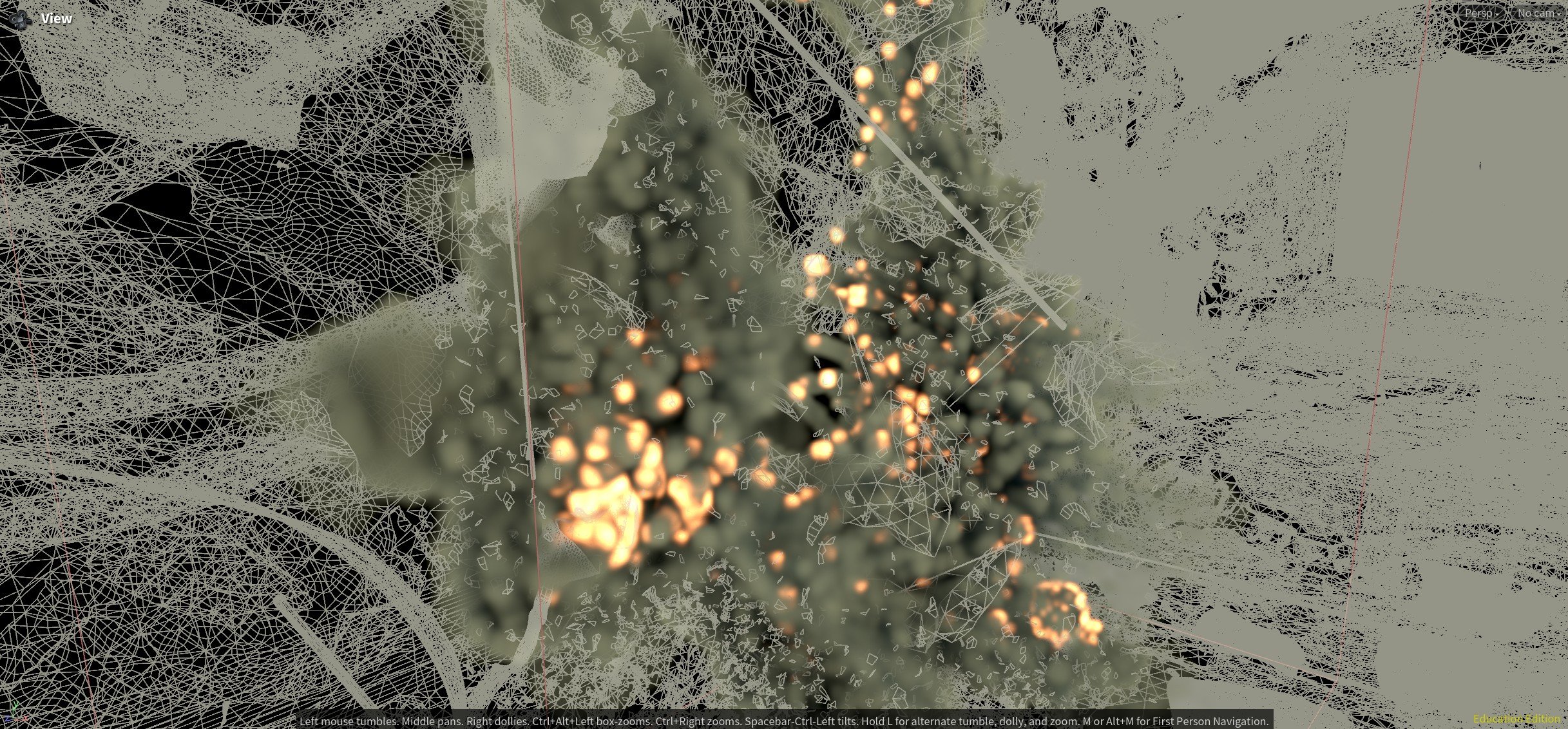
A digital art image featuring a layered composition with glowing orange lights, geometric wireframe structures, and a blurred background. The wireframes appear as interconnected lines forming abstract shapes and patterns.

Vellum is solved and cached for the frame range.

The vellum geo is packed and converted to VDB for quick collision calculation.

These collisions are brought into the explosion solver to ensure no clipping of the explosion and the vellum.

The vellum is then split into flammable primitives only by that material group.

We then bring in the baked and cached PYRO explosion volume as a primitives. These primitives become source overlaps for the fire spread.

I am using group creation and attribute creation to signify which points are and aren’t on fire.

These attributes drive the spread of the fire and track only to flammables.

Screenshot of a 3D object merge tool showing point, primitive, vertex, and group data for a 3D model.

Here are the network details at the top import geo for the SIM level.

Flowchart illustrating a 3D rendering process involving multiple steps like import of various elements, scene merging, material assignment, camera setup, and rendering, used for visual effects or animation production.

Here everything is brought into the LOP structure and prepared for Karma XPU.